The Blade Way Concept
During the past few years the market for servicing existing wind turbines has grown rapidly. One of the more significant market segments is for exchanging blades. Commonly, large mobile cranes are used, together with a blade yoke. The costs associated with the use of a crane are high, and so cheaper solutions are being sought.
By Per Fenger and Ruben Tjell Lambertsen, Liftra, Denmark
The already high costs of using cranes are often increased significantly by the groundworks necessary to improve the approach roads to the wind farm and allow access across the site itself. Availability is another issue when using large mobile cranes. It can take months to get the needed crane to the desired spot, due to the limited number of these cranes and the distance to the wind farm. One solution to the above challenges is to do away with the need for cranes by attaching pulley blocks to the upper blades and suspending two wires between these and two ground-placed winches. Two yokes are attached onto the wires, one for the blade root end and one for the blade tip end. The blade is clamped and secured by the two yokes which then transport the blade along the wires using the principle of a cableway – which is why the product is named Blade Way.
Set-up
Instead of having two cranes lifting, respectively, the root end and tip end yokes, two sets of wires are installed between the blades in a ‘bunny ear’ configuration and two winches placed inside a 40-foot container (the container also serves as the transport box for the yokes etc.). The two wires are used as a cableway for the yokes. Starting from the winches, these wires pass through hoist sheaves lifted by, for example, two telescopic loaders (to keep the blade tip free of the ground at take-off), through wire crawlers on the tip end yoke, through sheaves on the root end yoke, to the pulley blocks attached to the bunny ear blades. Two to three passes through of the cable (reevings) are made between the root end yoke and the pulley blocks to reduce the effective wire load to 3–4 tonnes when lifting a 14-tonne blade. Using this set-up, the wires are not only a cableway for the yokes but also lift both the yoke and the blade.
Manipulation of Blade During Lift
The crucial part of the set-up is the crawlers. These allow exact control of the wire lengths between the yokes and the winches and also between the yokes and the hub. This also means that the wire tension can be different on each side of the crawlers, which is essential. When the blade is close to the ground and in a horizontal position, the wire tension needs to be greater in the wire lengths between the yokes and the winches than it is between the yokes and the hub because of the reeving of the wires. When the blade is getting close to the installation position, the tension in the wire lengths between the yokes and the hub needs to be the larger, as they basically carry the full load of the blade and the yokes, while the tension in the wires between the yokes and the winches controls the blade angle.
Status
Most parts of this system are well-known and proven technology, but the crawlers are innovative. The idea of using crawlers to tension and position a wire has been around for several years under some of the following names: Capstan winch, Puller, etc. But in combination with yokes for blade handling and manipulation the idea is new. The first research into the system behaviour (yokes together with the blade), was carried out analytically. Wire forces and blade orientation were found for several positions, starting from the blade being at ground level to the blade being placed in the desired installation position. At the moment, the structural design has focused on what is needed when a 52-metre-long blade, with a maximum weight of 14 tonnes, is being carried between a root end yoke and a tip end yoke. With small changes in the set-up, the yokes can be adapted to fit blades down to a length of approximately 30 metres.
Scale Model to Prove Concept
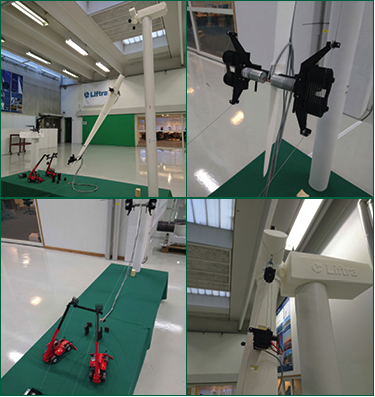
A 1:30 scale model has been made to introduce the concept to the wind turbine installation and servicing industry (Figure 1). The model consists of a turbine, a blade with permanently mounted yokes, crawlers, winches and two telescopic loaders. The wires are mounted, as they would be on the real set-up. The system is controlled by six actuators: two for the crawlers, two for the winches and two for the movable lifting points on the root end yoke. The actuators can be controlled either singly or in pairs with the remote controller using a microcontroller. In this way the scale model demonstrates the full functionality of the final product (Figure 2). The scale model is not only an eyecatcher for exhibitions etc., but also serves as a useful tool in the engineering process, giving us a better understanding of the mechanics and controllability of the winches and crawlers.
New Combination of Known Technology
Over the past four years Liftra ApS has gained valuable experience with the Liftra Self-Hoisting Crane (LSHC, Figure 3). The LSHC is installed in the nacelle and can be used to exchange the gearbox, generator, rotor and main shaft; jobs where a large mobile crane would previously have been required.
Common to the LSHC and the Blade Way is the use of the cableway technique. When installing the LSHC to the nacelle, this also travels along suspended wires from ground-placed winches to fixing points on the nacelle. The weight of the LSHC is also carried by the same wires as those used for building the cableway. The two ground-placed winches are placed inside a 40-foot container. The intention is to build future 40-foot containers, so that the same container can be used for both future LSHC and Blade Way projects. Liftra ApS has developed and built blade yokes for the last ten years and has a lot of experience on how to clamp and fix these in a secure and gentle way, so as not to damage the blade (Figure 4). The pad system on the Blade Way yokes will be a simple extension of this development.
The Future
It is planned to make a larger test rig at the beginning of 2016. The test rig will include a complete container with two winches, a 42-metre blade (cut down to 18 metres), crawlers and wire sheaves attached to the blade on simple steel structures clamping or bolted onto the blade, and two pulley blocks mounted on an existing test tower (simulating placement of pulley blocks attached to the ‘bunny ear’ blades). The crawlers will be full scale and will be able to be used afterwards on the final tip end yoke. The purpose of the test rig is to examine and prove the behaviour of the installation in a realistically sized set-up.
Biography of the Authors
Per Fenger started his career as an engineer at NEG Micon (now Vestas) after he graduated from Aalborg University in 2001 with a master’s degree in Mechanical Engineering. In January 2003 Per, and Jens Mortensen, founded Liftra, beginning with two employees. Today the company has around 60 employees in six countries.
Ruben Tjell Lambertsen joined Liftra in 2010 and he has participated in the development of blade yokes, where the work has covered project phases from the initial concept modelling, through calculations and finite element analysis, layout of electric, hydraulic and control systems, to commissioning and testing the yokes in the field. His background is a master’s degree in Electro-Mechanical System Design from Aalborg University, Denmark.