Latest Issue
 
Windtech International July August 2025 issue
 

Login


FOLLOW US AT

follow

 Follow us at BlueSkyFollow us at BlueSky


follow


Topology and Shape Optimisation to Speed Up Component Development
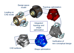
fedesignThis article addresses the challenging topic of new conceptual designs for wind turbine components, which aim to ensure price competitiveness as well as best-in-class structural performance. The focus is on the non-parametric optimisation approaches of the optimisation tool TOSCA Structure, created by the FE-DESIGN company. The main subjects of this article are two of the modules in that software tool: TOSCA Structure.topology and TOSCA Structure.shape.

By Claus B.W. Pedersen and Florian Jurecka, FE-DESIGN, Germany

{access view=!registered}Only logged in users can view the full text of the article.{/access}{access view=registered}Optimisation Methods

Topology optimisation is used in the initial design phase in order to generate new design suggestions. Based on the results of FEM (finite element method) analyses, the layout of the structural component is changed in a continuously repeated process until an optimal design is obtained. Optimisation targets could be to minimise mass, considering global and local stiffness demands, as well as dynamic properties, and taking into account manufacturing constraints. The use of topology optimisation in the early stage of the development cycle ensures fewer development cycles and lower costs.

Shape optimisation is a method for optimising detail improvements that can be applied later in the design process than topology optimisation. TOSCA Structure.shape modifies the shape (i.e. the outer contour) of the component, thus reducing local stress or damage concentrations. Accordingly, typical optimisation targets are stress or damage minimisation and hence maximising the safety-factor for fatigue problems.

The non-parametric optimisation methods are integrated into a fully automated optimisation process, which eliminates manual, time-consuming, trial-and-error procedures and thereby increases engineering productivity. With ‘non-parametric’ methods the designer does not have to define parameters as in a CAD (computer-aided design) model – the optimisation utilises the internal parametric of the CAE (computer-aided engineering) model and thus allows for full design flexibility. The most striking advantage of the non-parametric method is the ability to generate solutions at an early design stage leading to improved product quality.

A few selected numerical results of mechanical design applications for wind turbines are presented below. The examples given are the stiffness/mass relation for the main frame of a wind turbine, foam cores for blades, and fatigue minimisation of a planet carrier. Other typical parts where such optimisation techniques can be used are hubs (see Figure 1), shafts, bearings, pitch-mechanisms and drive trains including shafts, gearboxes and brakes.

Implementation
The non-parametric optimisation approaches are implemented as add-on modules to existing workflows of CAE and CAD designers. This allows the designers not to lose or disregard their existing knowledge of the validity of their CAE wind turbine models and their present knowledge of handling and executing CAE and CAD programs. The optimisation modules autonomously interact with the analysis results of CAE programs typically used for wind turbine design, such as ANSYS, Abaqus and Nastran. Additionally, the optimisation modules provide their results in a neutral format (IGES and STL) that is supported by all relevant programs such as CATIA, Unigraphics, Pro Engineer, Solid Edge, SolidWorks, etc. This allows time savings and efficiency improvements.

Topology Optimisation
Topology optimisation determines an optimum design suggestion starting with a definition of the maximum design space. The design space geometrically defines the volume in which the structure is allowed to be placed. When creating the design space not much time is spent in generating geometrical details as the topology optimisation automatically creates all geometrical details during the optimisation.

In topology optimisation the finite elements are design elements which are ‘added to’ or ‘removed from’ component parts. During optimisation, the relative density of each element changes, while elements of low density are eliminated and only elements of high density form the final supporting structure. All loads and boundary conditions from the FEM are taken into consideration during the automatic modification procedure. Topology optimisation aims to arrive at a new conceptual design achieving stiffness, reducing weight or optimising dynamic properties, etc. During the optimisation process standard manufacturing methods can be defined as requirements. These include techniques like casting, stamping, drilling, turning, etc. Topology optimisation with TOSCA Structure.topology allows all three types of nonlinearities: contact, geometric and material nonlinearities.

Best Stiffness/Mass Relation for Main Frame
The main frame is one of the most common structural components designed using topology optimisation. The reasons for this are to obtain significant stiffness improvements, decrease the weight of the frame, and include or change the manufacturing constraints in the final design. Figure 2 shows a conceptual design cycle of a main frame for the Indian wind turbine manufacturer Suzlon. The first step in the design cycle is to define the design space in which the new main frame is located. Then the topology optimisation is executed where the stiffness is maximised over several load cases.

Conceptual Design of Foam Cores for Blades
This example (see Figure 3) shows how topology optimisation can be applied to the conceptual layout design of the cores of the blades. Different criteria can be applied to the optimisation (e.g. minimising the mass, desired eigenfrequency properties, and global, as well as local, stiffness requirements). Different optimisation set-ups for a blade optimisation could be deflection minimisation, increasing the natural frequencies, or a combination of increased first and second eigenfrequencies.

Shape Optimisation
Shape optimisation allows specific detail improvements of existing designs. The non-parametric shape modifications of TOSCA Structure.shape are performed automatically in interaction with the FEM simulation where each surface node can be displaced independently. This allows for maximum design flexibility. The program ensures though that the finite elements inside the part are not significantly distorted by changing the component surface. In each step the finite element mesh is adapted by an automatic mesh smoothing algorithm. Normally, the objective in shape optimisation is to minimise the maximum stress or minimise the damage and, thereby, maximise the safety-factor for fatigue problems.

The often small, but important, changes in the surfaces of an existing design lead to major reductions of local structural properties like stresses, damage, strains and contact pressures.

Nevertheless, if, for example, the objective for the designer is to minimise the highest stress and thereby remove stress hotspots, often this cannot be achieved efficiently by parameter variation. Thus, the non-parametric concept, with its full shape flexibility, is required to achieve significant design improvements. For this TOSCA Structure.shape modifies the shape of the part by moving selected surface nodes – typically in less than ten iterations.

Fatigue Minimisation of a Planet Carrier
TOSCA Structure.shape supports fatigue optimisation – both for commercial fatigue and in-house fatigue solvers. The optimisation considers complex loading histories to minimise damage or maximise safety factors. Figure 4 illustrates the different stages of the automated iterative design process for a planet carrier using shape optimisation to increase durability.

Conclusions
Topology and shape optimisation lead to an efficient design process for structural wind turbine components. They do this by obtaining:

  • optimised and best possible structural properties
  • excellent mechanical designs
  • lower cost of materials
  • automated design and simulation process
  • increased engineering productivity
  • early decisions in the design cycle
  • less trial-and-error procedure in design
  • reduced design and manufacturing costs
  • shorter development time.
Biographies of the Authors
Claus B.W. Pedersen has a MSc and a PhD in Mechanical Engineering from the Technical University of Denmark (DTU). From 2002 to 2004 he undertook research, first at DTU, and then at Cambridge University in the UK. In 2004 he joined FE-DESIGN working in various aspects of research and development. He is currently head of Nordic Operations, based in Hamburg, Germany, where he manages R&D projects for new optimisation tools and provides solutions for wind turbine manufactures and suppliers.

Florian Jurecka has a doctorate in the field of numerical structural optimisation, and a Dipl.-Ing in civil engineering. For nearly six years, from 2001, he was a Research Associate at the Technische Universität München, and since then he has lectured at the same university on structural optimisation. He joined FE-DESIGN in 2007 as Senior CAE Engineer and Project Manager for simulation and optimisation and in 2009 was appointed head of FE-DESIGN, where he initiates and supports national and international pre-sale activities and projects.{/access}
 
Use of cookies

Windtech International wants to make your visit to our website as pleasant as possible. That is why we place cookies on your computer that remember your preferences. With anonymous information about your site use you also help us to improve the website. Of course we will ask for your permission first. Click Accept to use all functions of the Windtech International website.